The Ray.tura

LUCIDARE LE CROMATURE
19 Aprile 2020
Catalogo Ganna 1924
2 Maggio 2020THE RAY. TURA
The term beam is the number of intersections that make a radius before reaching the circle. Since the choice of one type of ray.tura over another affects the length of the rays, it is good to understand the differences and the destinations of use, so as to define the best for us and for the wheel that we are going to build. In this case, when talking about vintage bikes, we will focus on the most used rays or rays. The fourth-in-the-back beam is usually used in the rear wheels, which are subject to traction and stress, which requires more stiffness. As necessary tools we will use: – Tiraraggi – Central wheel (even a fork placed backwards in vice can be fine)
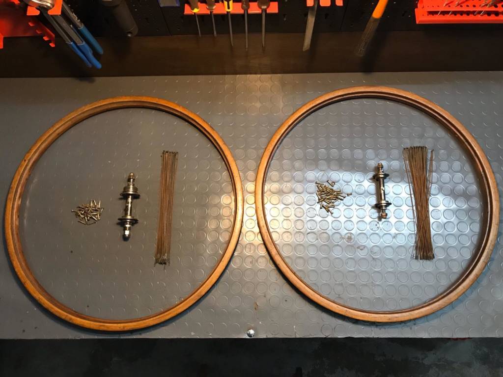
Before we begin the beam. In our case the hubs can be from 36/36 holes or 40/32 whose number of rays we would need will always be 72. It is also important to understand the diameter of the rays with their respective niples: if the rays are 1.8 mm (15 Gauge) we will use niples with 1.8mm thread (15 Gauge), respectively with 2mm rays (14 Gauge) we will use 2mm (14 Gauge) niples. NB: Be careful with the threading because the 2mm niples are mistakenly screwed even on 1.8mm rays this factor is due to the small difference of thousandths of mm that there is between one and the other, but with a finished wheel it involves the failure of the same and therefore the breaking of rays, hubs and so on…
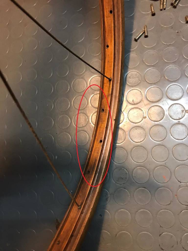
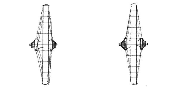
Well let's get started…. We are beaming 26×1/2 wheels with 285mm x 1.8mm beams with respective niples (longer because we treat wooden rims) and 36/36 hubs. These circles have holes not perfectly aligned in the center, in fact they have different positions this to follow the beam.

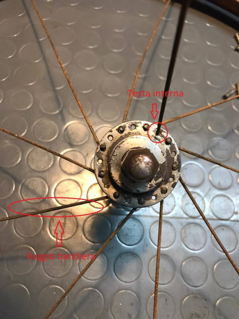
Let's start with the rear wheel, take the hub we insert a beam with external head into any hole and insert it immediately after the valve hole, in the first available hole with the verse in which we are beaming. (upwards)
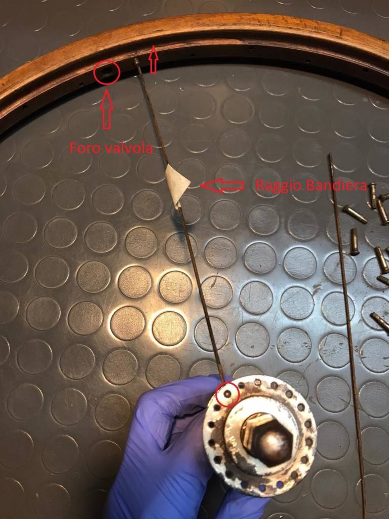
We continue leaving a FREE FORO, we always insert with an external head and insert it into the 4th hole following the flag radius always with the right direction.

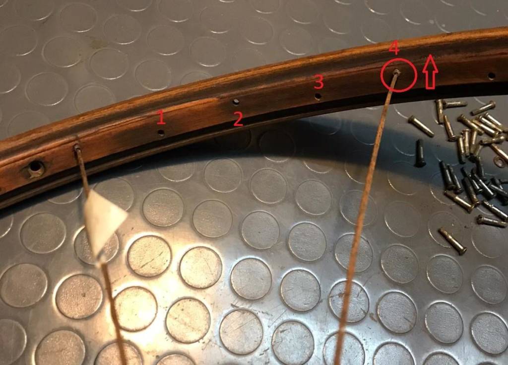
I recommend not to tighten the niples too much because they may prevent the insertion of other rays because of too much rigidity. Let's continue with the sequence: insert external head radius leaving a free hole on the hub (where the ones with inner head will later go) leaving THREE holes free on the circle.
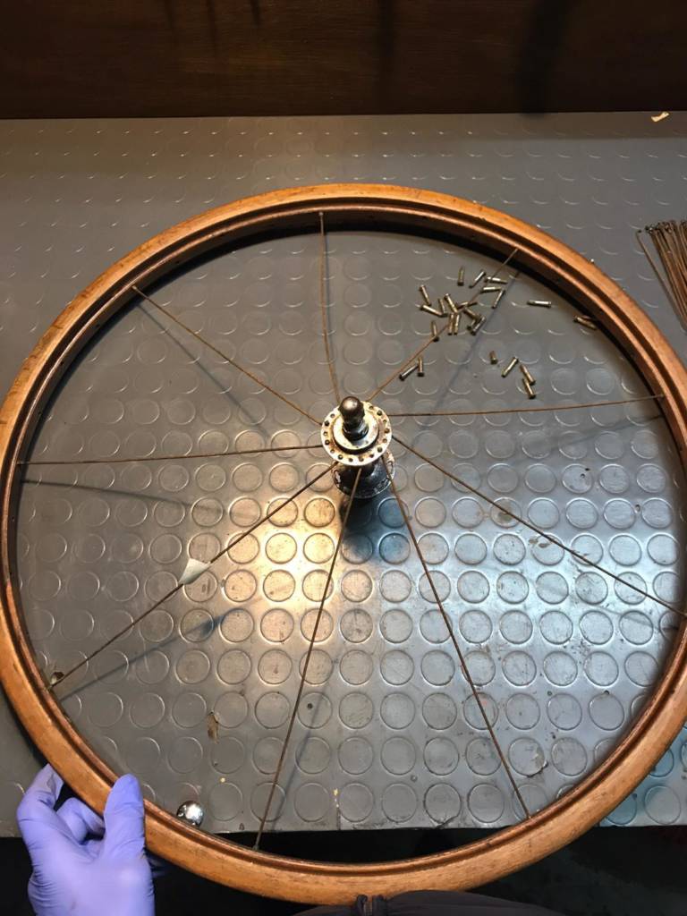
Now we rotate the hub in the ANTIORARIO direction in order to spread the rays well.

At this point we are going to insert the rays with the inner head, being the beam.
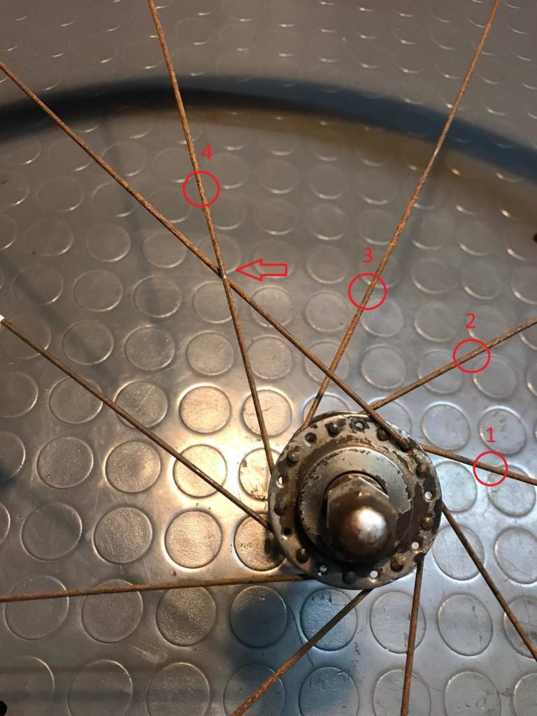
This beam will always pass the first 3 spokes and ONLY the 4th radius, and two holes after our flag radius will be inserted. (always check the hole verse for safety)

We always continue with the same sequence when the other rays are inserted with the inner head.
At the end of the beam, we check that there are always a free FORO between one beam and the other, the opposite of that of the beam.

Now let's move on to the beam.tura from the opposite side: we take a radius we insert it (ONLY FOR TAKE THE SIGN OF THE FORO IN CUI ANDREMO TO INSERT THE RAGGIO WITH INTERNAL TESTA) with external head marking with the tip of the radius to the RIGHT part of the flag radius, and that's where we're going to insert the FIRST radius with internal head.

NB: In this case, as it is a hub with special holes on the side of the free wheel, the first radius with the inner head will be inserted into the left side circled in the photo. Inserted the radius will be inserted into the hole after the starting radius.

From here in the ANTIORARIO sense we will count 10 holes and insert them our beam with EXTERNAL head that will be inserted into the hole before the valve hole.

We continue with the insertion of the rays with external head always placing them 4 holes forward (Always counterclockwise) at each radius inserted with external head.

After inserting all the rays with external head we continue with the same procedure written above with the insertion of the rays with INTERNA head. Remember… the radius passes over the first 3 and below the 4th, the latter should be inserted in the first hole before the 4th radius that crosses, practically it would end by occupying all the free holes with the rays with internal head.
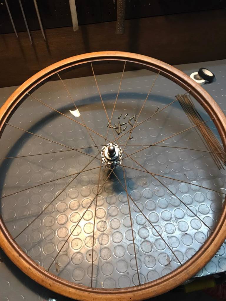
Our wheel is finished now we just have to center it and bell it.

For the front wheel we will go to do the same procedure only that it is beam.
NB: The insertion of rays with external head is IDENTICAL.

In turn, the first two rays pass through and the 3rd radius WILL pass. (ALWAYS IN AN ANTI-TIMELY SENSE)

To complete the wheel in TERZA use the same and identical procedure described above for the rear wheel by changing only these two steps shown in the photo.
CENTERING AND CAMPANATURA
As an initial phase we have to tighten all the niples without exaggerating to balance more or less all the rays, at this point by rotating the wheel we will notice that the circle will have huge oscillations both to the right and left, NOT PREOCCUPATEVI is all normal here you will have to start tightening the rays from one side to the other so that you center it as much as possible in this way : – At the point where the wheel for example pulls more from the right side you should tighten in that part the niples of the left rays and give up the rays from the right side, in the part where it pulls more to the left you should do the reverse work i.e. give up the niples in the left side and tighten those of the right side. Once you have eliminated the large oscillations to eliminate the small remaining oscillations you will have to follow the same procedure listed above however doing small turns/half turns of niples this in order not to destabilize the half centering that has already been carried out. – Once centered, you have to adjust the jumps of the circle, that is, those voids that are created when the wheel spins and that can sometimes even ovalize the circle if the niples have not been squeezed evenly. Where you create the void you have to go to give up the niples while where the circle lowers too much you have to go and tighten them, obviously this procedure is a little complicated to understand from a theoretical point of view but I assure you that with small notions and practice comes a fairly satisfactory job. – the last step is the ringing of the wheel this allows you to understand if the hub is well centered to the rays and the circle respectively. As you can see the wheel in the left photo is escaped to the right so you will have to start from a radius (I always recommend the closest to the valve hole as a reference) is so UNIFORME drop every radius, for example, half a turn, of the right side and always screw the niples of the left side by half a turn, at finished work if you see that the wheel is still escaping proceed with the same method increasing or decreasing the number of laps for each radius during screwing/unscrewing.
For the final verification of the bell by eye already would be fine but if you want to be more precise you use some tools for sale online or from retailers like the one in pictures

Full file in pdf: LA-RAGGIA. TURA